Raspberry Pi thermostat - Building the hardware
This blog is about building my own thermostat with Raspberry Pi. This is part 1 where I explain the hardware. Part 2 talks about how I build the software that controls it.
What did I not like about the mercury thermostat?
I didn't like my old mercury-based thermostat for a couple reasons. First, the temperature fluctuation was pretty significant, up to 3 degrees C because mercury takes a while to react to the temperature change, Also I didn't like having to go to the living room to adjust the thermostat all the time.
Why did I not just use Ecobee or Nest? This was for fun & to learn how to build basic electronics using RPi ;)
Prerequisite
The interface to the HVAC is a simple single stage 4-wire control.
heatresistive heat strips - white - not used- fan - green
coolingheat pump - orange- power - red
Thank you /u/Nephilimi for the correction.
Basically, you just need to connect the power wire to what you want to turn on.
Connecting power to
heat or
cooling will heat/cool your coil.
Since I live in an apartment equipped with a heat pump, connecting power to heat pump will cool in summer and heat in winter.
Then you also need to run the fan for the air to circulate.
Parts needed
- Raspberry Pi - it can be any model really, but you want wifi for remote control.
- You need 3v, 5v, GND, and 4 GPIO pins minimum. 7 more for a 1602 display.
- Soldering equipments (example)
- Lots (10~20) of female to male jumper cables (example)
- Wires - I just used a 22 gauge wire
- Prototyping board (example)
- 3 x 2.2k and 3 x 10k Resistors
- 3 x 2n2222 NPN transistors
- DHT11 digital temperature & humidity sensor
- Minimum 3 channel relay (this is what I used)
- A 1602 display, if you want to display status also. It's named 1602 because it displays 2 rows of 16 characters.
Circuit
Here's the schematic for the core parts:
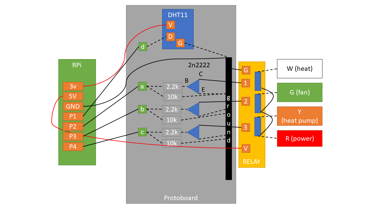
Solid lines denote where I had to use a wire. Dotted lines denote where I didn't have to use a separate wire thanks to either the board or existing wires.
Pins
P1 ~ P4 denote any free GPIO pins.
- 3.3v to power DHT11.
- 5v to power the relay.
P1communicates with DHT11 (both read/write).P2~P4controls the three relay outputs.
Communicating with DHT11
DHT11 needs only one data pin because it both handles input and output through the same pin.
Controlling the relay
This was the only non-straightforward part that required a bit of thinking. When the relay is powered, the switches are simply disconnected. In order to 'close' (or, connect) the switch, you need to drain the current from the relay pins.
This is where the NPN transistor helps. It has 3 parts: base (B), current (C) and
emitter (E). Electricity flows from C to E, only if voltage is
applied on B.
In this case, C accepts current from the relay, but it doesn't let it go through
E unless B has voltage. And we control the voltage by setting the line high
from the Rpi.
So in my circuit, asserting P1 high connects power to
heat. P2 and P3
controls fan and cooling
respectively.
Finished hardware
Here's a ghetto looking finished thermostat in action:
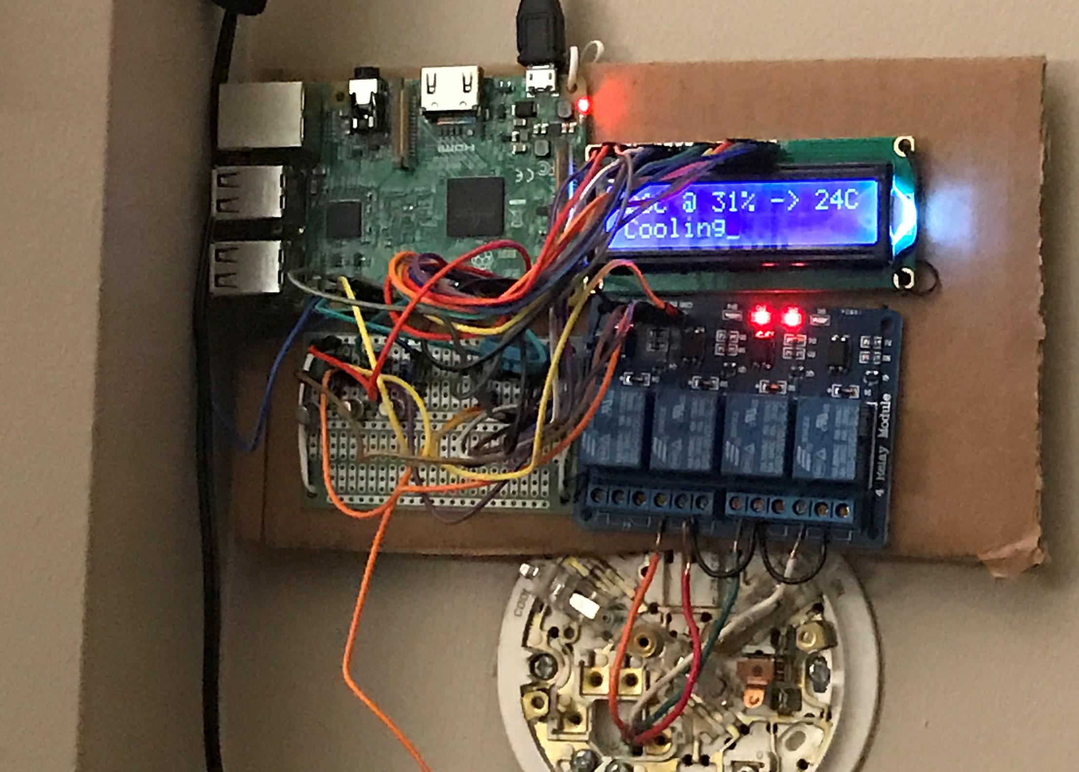
Due to my lack of any real hardware skills, I could not put together in a more polished way.
What's next?
Check out the part 2 for the software that runs this thermostat.
Recent posts
Categories
Search